Davis Mechanics and Loop Holes in the Third Law of Motion
Edward M. Renner
Original: 4/1985; Revised: 9/2011, 10/2013, & 1/2014
Introduction
There are many grey areas in classical Newtonian physics that cannot explain anomalous mechanical behavior or transient phenomena. Yet, from investigation of some of these anomalies have come innovative ideas and new concepts which have expanded the scope of classical physics to include relativistic physics… and the concept of inertial drives. The concept of an inertial drive has been around for many years, from science fiction to dozens of interesting inventions and devices. Most of these inventions usually depend on known scientific phenomena to manifest their apparent violations of the laws` of motion (i.e., slip-stick friction, precession). However, when anomalous phenomena (deviations from theory) consistently occur under specific and controlled experimental conditions, it is probably the mathematical model that is at fault or incomplete, not the results; thus experimentation with inertial effects and other discoveries in the engineering field (when the existing paradigms failed to explain experienced phenomena) have also resulted in a rethinking/reformulation of time honored mathematical theories and classical motion laws. Although the concept itself is simple, its reality appears to violate what we accept as classical laws of motion/ momentum (i.e., 3rd Law); thus has generally been ignored, ridiculed, or explained away by most theoretical scientists. However, there are many examples of special case / apparent violations of motion laws from the annals of engineering and science, and there are many simple proof-of-principle devices that can be, and have been, created to demonstrate these apparent violations and isolate the phenomena of interest. The governing principles of real inertial drives were perhaps best summed up mathematically by William O. Davis in his Fourth Law of Motion (1962, Davis Mechanics); a law that accounts for the various transient and anomalous inertial effects seen in real physical systems (see Discussion).
This paper is a review of angular momentum translation principles/ experiments, the transient effects seen in forced harmonic driving forces, and the theoretical foundation of inertial drives; plus speculations on the consequences and applications of such drives.
Principles and Devices
Conservation and Conversion of Momentum
The Conservation of Momentum is a principle that has real applications only at relatively low velocities and under idealized conditions. This is quite apparent when you consider that momentum (mv) is converted in a high velocity impact, via kinetic energy (mv2/2) and friction, into random molecular momentum (heat). Thus the conservation of momentum is a principle with many exceptions in physical reality, and is simply a reflection of the conservation of total energy (SE); i.e.,
ES 1 = [mv1]~ mv12/2 --->[mv2] ~ mv22/2 + ΔH = ES 2 ; mv2 < mv1, but ES 2 =ES 1
Therefore, the conversion of angular momentum into linear momentum (a proven principle) without an intermediate factor (i.e., friction, impact) is not a violation of any physical law if total energy is conserved.
ES = Iw12/2 -à linear conversion ---® Iw2 2 /2 + mv1 2/2 = ES
One way this conversion can be demonstrated is by amplifying certain transient effects found in rotating masses undergoing forced harmonic and precessional motion.
The Drive Wheel
The simplest form of translation of angular momentum (Iw ) to linear momentum (mv) is demonstrated by the ordinary drive wheel; e.g., the wheel of a car. In order for a car, bicycle, or train to move forward, the angular momentum generated by the engine/driving force and imparted to the wheel must be translated via friction and contact with the frictional contact surface (the road, rail, etc.). This happens by a maximum deceleration of the wheel occurring at the interface of wheel-to-surface and a transfer of energy via friction. Maximum acceleration in the wheel occurs at the opposite side of the wheel’s contact with the frictional surface, thus during a rotation cycle of the wheel, one side is at maximum angular velocity while the other side is at a minimum. The net result is that angular momentum is translated into linear momentum/ motion via the intermediary of friction. The actual changes in acceleration and deceleration are real in frictional contact surfaces that are elastic or semi-elastic, but are likely manifest as virtual changes or stored static stress forces when contact surfaces are inelastic, i.e., a steel train wheel. This is a key concept when looking to reassess the conservation of momentum, for in order to have a rigid/inelastic wheel function, there is probably a decoupling of actual and virtual centers-of-mass (or cg from cm).

FIGURE 1 - Angular to Linear Momentum in the Drive Wheel via Friction.
The Pendulum/Swing
The pendulum provides an elegant proof of energy conservation and compliance with the basic laws of motion, but it can also be used to demonstrate the effects of a harmonic driving force, translation of one form of energy to another (which the pendulum depends on for its operation), and the amplification and conversion of angular momentum into unidirectional momentum and vice versa.
A functioning pendulum utilizes gravity (g) to transform potential energy (PE) into kinetic energy (KE)/momentum (mv/Iw ) and then back again as it completes one cycle of oscillation (simple harmonic motion). A pendulum bob in motion gradually loses energy due to air resistance and friction; but can be made to oscillate continuously if a small driving force, such as an impulse from an electro-magnet, is used to replenish the energy lost (a Foucault pendulum uses this method to operate). The pendulum can also be made to oscillate from rest by translation of bob internal energy/momentum into mv/Iw via a harmonic driving force; i.e., if the bob of a pendulum is a hollow sphere which contains a smaller mass which oscillates back-and-forth and provides a harmonic driving force at the fundamental frequency of the pendulum, the pendulum will move from rest and oscillate in increasing amplitude (like a child’s swing when the child shifts its’ center of mass to-and-fro at the fundamental frequency of the swing). Also, if an eccentric rotating flywheel is substituted for the linear oscillating mass inside the pendulum bob, the pendulum will oscillate in an elliptical/circular fashion (a conic pendulum) if the rotation rate of the eccentric flywheel is matched to the fundamental frequency of the pendulum. This type of harmonic driving force will produce oscillations of increasing magnitude (limited by the balance between potential and gravitational forces) which essentially is an angular Iw deflection of the “static” acceleration produced by gravity.
Further, if the string that holds the sphere in both of the above systems is cut at a point of maximum kinetic energy/angular momentum, the bob will travel in a tangential (straight) line with equivalent linear momentum (just like a child launching himself off a swing). So it would seem that internal oscillatory momentum may be amplified and stored in a pendulum/ swing via gravity and simple-harmonic-motion (SHM) and then released as linear momentum; thus demonstrating the production of angular momentum and its’ conversion to linear momentum from an internal power
source.
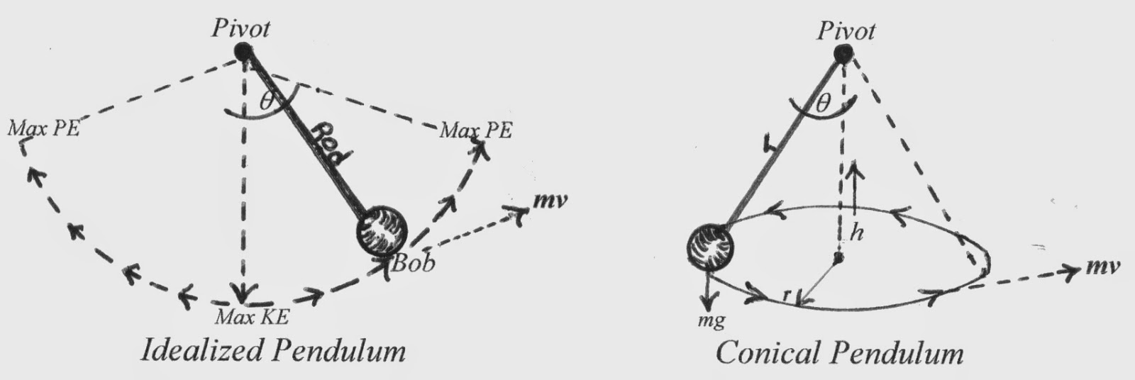
FIGURE 2 - Pendulum Motion and Momentum Conversion
The Gyroscope
Another common device which appears to violate the laws of motion is the gyroscope. If a force vector is applied to the axis of rotation of a gyroscope operating at speed, the action becomes translated not to an opposite and equal reaction, but rather to a reaction that manifests itself at right angles (90°) to the direction of applied force; i.e., gyroscopic precessional force. The 90° deflection of the force (q ) appears to be an asymptotic limit for the gyroscope (and one that is apparent in other devices), and higher rotation speeds do not deflect the applied force beyond that value. This is a phenomena that is also seen in flywheels at high rotation rates.
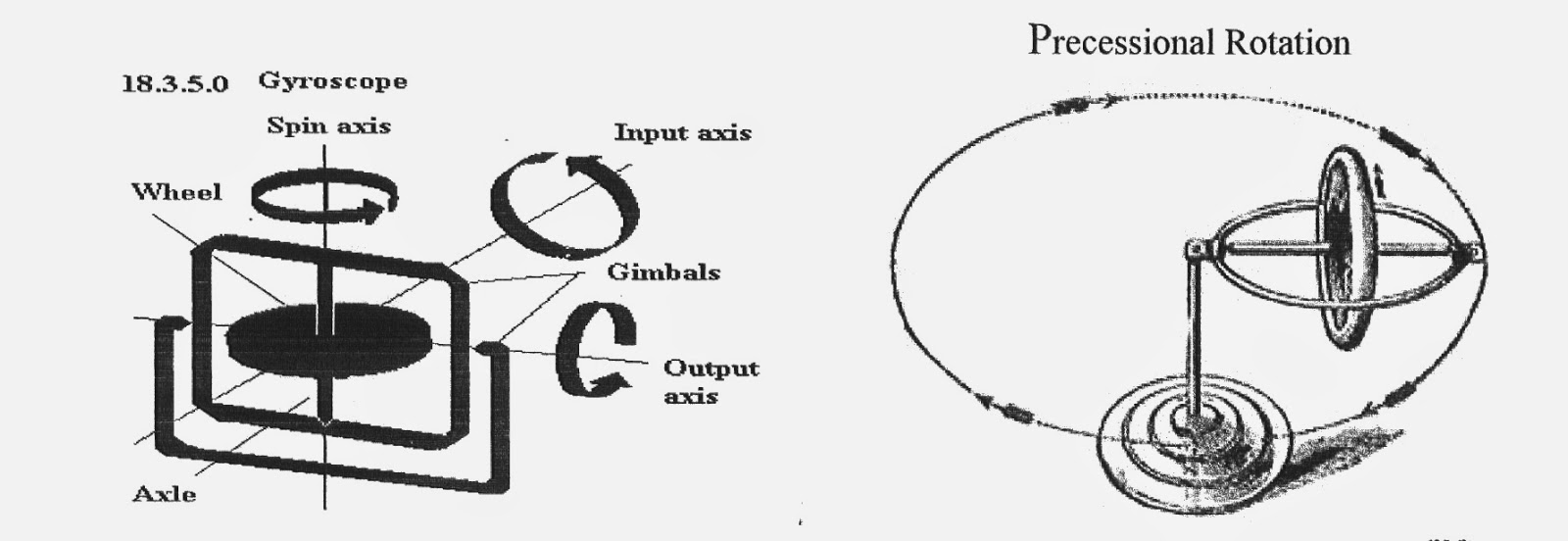
FIGURE 3 - Translation of Force vector in a Flywheel/Gyroscope - IAW the right hand rule of gyroscopic precession, applied force (Input / mg) is translated into momentum at right angles to the plane of rotation and force (Output / precession).
Force Precessed Gyroscopic Devices
If two counter-rotating gyroscopes are linked together so that they form a single system, with the gyroscopes separate but free to either move apart, towards each other, or pivot at angles on their axis’s, and then two opposing forces are applied to move the gyroscopes, i.e., springs, magnets, solenoids, cams…, the dual gyroscope system translates the opposing forces into a unidirectional force at right angles to force application IAW the right-hand rule of gyroscopic precession (as in Kidd‘s Force Precessed Gyroscopes- see Fig. 4 & 5). This phenomena is different than the effect of shifting the cm in a closed system because the cg of this system remains constant (between the gyroscopes) and it is the two opposing forces that are translated into a combined precessional /
directional motion/force.

FIGURE 4 - Dual Counter-Rotating Gyroscopes (Phenomena
testing) - Springs drawing
gyroscopes together/tilting produce unidirectional precessional
force; magnets, solenoids, or cams may be used for the same purpose.
If two 180°
opposed counter-rotating steel flywheels are spun on a secondary
axis and an electro-magnet is positioned above and between the
gyroscopes, opposing magnetic impulses can be delivered to the axis’
of rotation through the masses. This should have the effect of
producing linear precessional impulses and a robbing some of
the angular momentum for conversion into linear momentum via the
magnetic impulses. (see A. Kidd, US Patent 5024112A, 6/18/1991 and
Fig. 5.).

FIGURE 5 - Force Precessed Gyroscopes -
Simplified schematic of Kidd device
but using magnetic Force instead of mechanical). Centrifugal action
on the gyroscopes acts as a restoring force countering the magnetic
impulses.
The dynamics of even a single gyroscope are quite complex
and those of gyroscopic systems, such as those above, can be so
complex and potentially confusing that building them may be easier
than describing them mathematically. This is where trial-and-error
experimentation comes in, and it may be more advisable to explain
experimental results after-the-fact and with real data than trying
to predict results mathematically; which may appear to violate
fundamental concepts of motion and momentum conservation and for
which Newtonian mathematical theory may only lead to the null
hypothesis.
Rotational to Oscillating
Circular and Bidirectional Motion
If a rotating flywheel is placed upon a frictionless table and
has its center-of-mass (cm) displaced from the axis of
rotation, the flywheel is unbalanced and at low speed will
oscillate in a circular fashion about the center of gravity (cg);
with the rate and magnitude of oscillation corresponding to the rate
of flywheel rotation and degree of cm displacement. Therefore,
the greater the displacement of the cm, the greater the out-of-balance
condition and oscillation. However, in this form of forced harmonic
motion, the cg of the system can be seen to lag behind the axial
driving force by a phase angle
φ. Even at low
rotation rates, such an oscillating system can be made to achieve
apparent unidirectional motion if the driving force of the
system is varied in synch with the fundamental frequency of the
system and slip-stick friction factors are considered [as anyone can
testify who has slid themselves across the floor on a chair by
suddenly shifting their weight]. However, when the rate of rotation
of the unbalanced flywheel is increased, the actual oscillation/displacement
of the whole system starts to dampen and can virtually be
extinguished at very high rotational rates due to the inertia of the
system and gyroscopic stabilization; i.e., the system is unable to
translate the inherent inertial forces into actual displacement due
to the rapidity/rate of change in direction of the forces, thus
φ can be seen to
grow to a maximum value of 90°.
The result of such a dampening effect is that the actual
center of gravity of the system appears to decouple from the
center-of-mass, and the rotating flywheel tends to center
itself around the torque force, while the virtual center-of-gravity
(of the system) continues to oscillate.
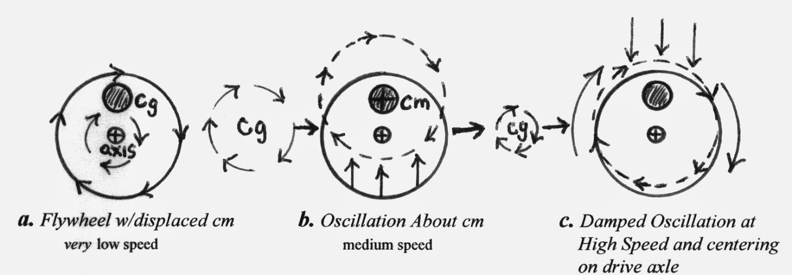
FIGURE 6 - Oscillation in an Eccentric Flywheel -
Note c., angular momentum about the
axis has a tendency to center the mass about the rotational axis.
φ
Iw> mv
Further, if two counter-rotating eccentric
flywheels are linked as a single system where the actual center-of-gravity
of the system lies between the cg’s of the two flywheels, the
oscillation of the system is transformed into a bidirectional
motion that manifests itself tangentially to the masses and
through the system cg travel line (Fig. 7). This
bidirectional change of cg (forced harmonic motion) resembles
the accelerated motion of a loaded oscillating spring (accelerating
and decelerating bidirectional motion) and can be described by the
inclusion of a spring constant (k) in the motion equations (see
Discussion). Further, like the dampened oscillation of the
single eccentric flywheel at high rotational rates, the actual (bidirectional
moving) cg of the dual-system is also decoupled from the
cm and dampened at higher counter-rotational rates, while the
virtual cg continues to oscillate bi-
directionally.
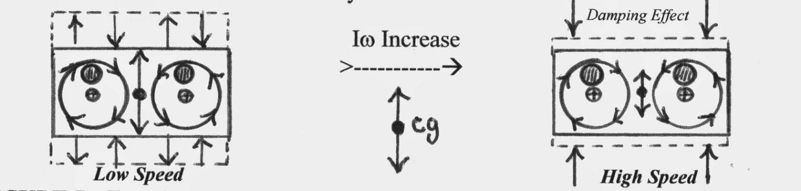
FIGURE 7 - Two Counter-Rotating Eccentric Flywheels -
Rotary oscillation is cancelled by
counter rotation of masses, and bidirectional oscillation is
dampened at high speeds and manifest as stress force at the axles.
Counter rotating flywheels may also be stacked one on top of the
other.
Counter-rotating eccentric mass devices, such as the above,
usually have very limited application (they tend to shake themselves
apart or produce unacceptable vibrations); but when used as
mechanical oscillators (called Buehler Drives), the
bidirectional impulses they produce can be harnessed to set up truly
massive resonant/ harmonic oscillations, and have been used to
simulate earthquakes when attached to large structures (if the
rotational or oscillation velocity of the device is matched to the
fundamental harmonic frequency of the structure).
Also inherent in this dual counter-rotating mass system is a
phenomena that depends upon the direction of the converging counter-rotation
of the system and is manifest as a small net transient impulse
(surge / precession?) delivered along the line of travel
of the cg and in the direction of convergence rotation; and
this impulse may be amplified by modifications to the system that
enhance the effect.
Rotational to Unidirectional
Motion
Although the effect of forces acting on a balanced rotating
flywheel/gyroscope are hard to characterize mathematically, it can
be simplified by viewing angular momentum instantaneously and as an
infinite series of opposite but equal inertial vectors that are
manifest tangentially to the direction of rotation of the spinning
flywheel/gyroscope. However, if we consider the unbalanced flywheel
with a decoupled virtual and actual cg, and then induce
cyclic perturbations in the cg, we find that the stage is set
for loopholes in the 3rd law of motion because of the inability of
any system to completely absorb or respond to rapid inertial changes.
Thus many rotating systems can be made to manifest net
unidirectional force/motion in apparent violation of the Third
Law of Motion; these apparent violations are, however, just
transformations of one form of momentum into another (angular to
linear) and re-vectoring/deflections of the reaction to applied
forces (as in gyroscopic precession).
Dean Drives - Mechanical Phasing [FHM]
One way to achieve the above effect is to mechanically link and
unlink an eccentric counter-rotating mass-system to a secondary but
encompassing subsystem during the cm convergence portion of
the rotation cycle, and in such a way that both systems become one
during the linked portion of the cycle and separate systems during
the unlinked portion. This type of system is rather finicky and
operates on purely phased mechanical inertial forces, but has been
demonstrated by many patented working models such as the Dean Drive
and Hampton’s Inertial Engine (ref. Dean, 1959; Stine, 1969;
Harrington, 2011) Upon examination, I believe some of the more
obvious net effects that have been demonstrated in these devices may
be manifestations of slip-stick friction, although some (the quoted
models) seem to truly demonstrate inertial drive effects.
Magnetic Coupling in Buehler-Type Drives [FHM]
Rotational angular momentum can also be transformed into
unidirectional linear momentum by utilizing a dual counter-rotating
eccentric mass system that is magnetically coupled and decoupled to
the to the non-rotating part of the system during a portion of the
flywheel's rotation cycle; so that a net impulse is created in the
whole system and in one direction - much like Dean-type devices. At
high speeds the opposite reaction impulse can be split and
manifest as force vectors at a phase angle (j
) to the net linear impulse, thus producing a net opposite reaction.
Optimum coupling/ decoupling to achieve a maximum net impulse can be
obtained by experimentation, but probably lies somewhere around 1/2π
Rad of the rotation cycle during cg convergence and at the
bidirectional cg centerlines. By using non-magnetic plates (e.g.,
aluminum) with iron plugs or permanent magnets at their periphery to
cause the out of balance / eccentric condition, and by minimizing
the loss of angular velocity/momentum during the cycle, the magnetic
translation effects can be further isolated, amplified, and directed.
Such a device can be configured as stacked counter-rotating plates
with the same offset cg’s, and can also be setup as a permanent
magnet motor using electro-magnets to both rotate and cause variable
momenta during the rotation cycle via an adjustable commutator. The
weights in the platters can be exchanged for magnets (permanent or
electro-) to further enhance the angular momentum and effects.
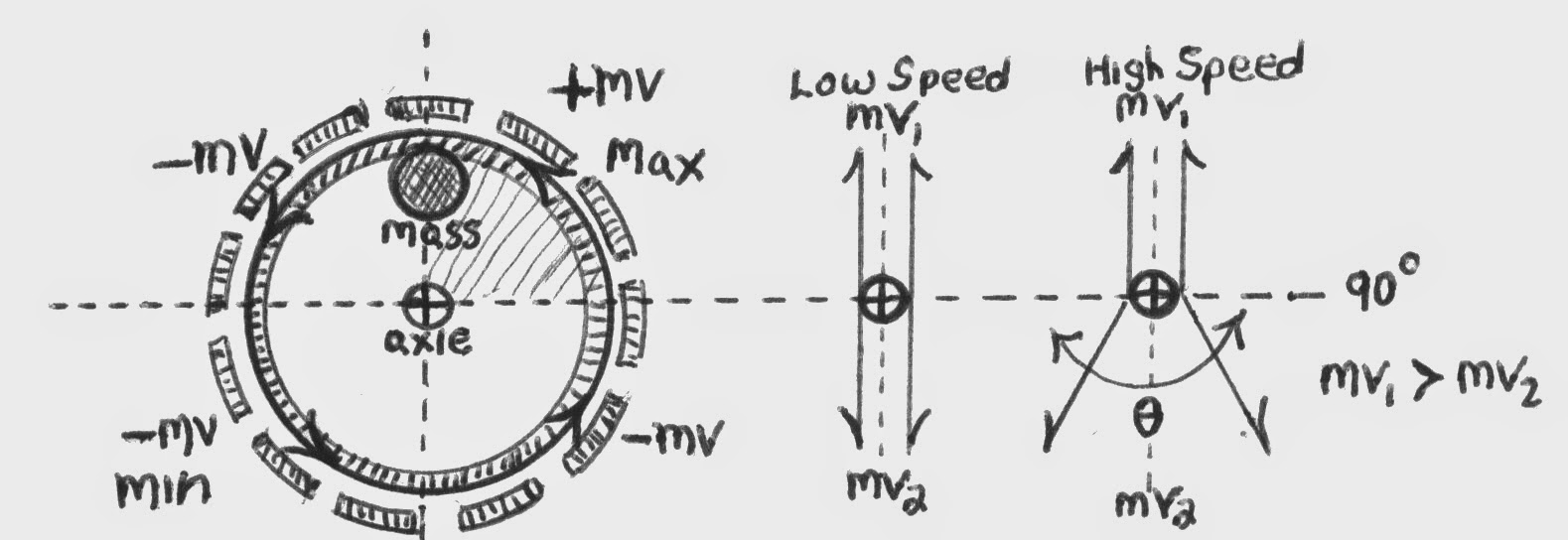
FIGURE 8 - Stacked Eccentric Counter-Rotating Plates
- Permanent magnet motor type system. Magnets can be used to
both accelerate and decelerate mv at opposite poles to create off-set
Iw /mv. Permanent magnet
motor can control rotational cycle and perturbations via an
adjustable commutator.
Centrifugal Devices
Another means of translating rotational to unidirectional
momentum has been demonstrated by utilizing horizontally mounted
counter-rotating platters with free-swing weights attached off-center
by eccentric pivot points. If the platters are rotated at a proper
speed for the system, the weights are flung outward and then
continue swinging and are drawn inwards by the angular momentum of
the platters (working in conjunction with the eccentric pivots)
towards the platter’s centers. These free-swinging weights are made
to undergo one orbital revolution per rotation of the platters (see
Figs.9a & 9b). According to the inventor, the counter-rotation of
the platters negates all forces except a unidirectional one (Gilbert,
1985). The unidirectional force produced by this device depends upon
an offset and increase in momentum during the outward swing; i.e.,
variable momentum (Iw) over the course of the orbit. Such a system
may not work effectively (or at all) at high rotation rates, as the
weights would be unable to respond to the rapid inertial changes in
their eccentric orbits, thereby limiting high performance
applications. However, this device does demonstrate in a simple and
elegant manner the principle behind other more complex inertial
drives.

FIGURE 9a- Counter-Rotating Platters With Free-Swinging
Weights & Eccentric Pivot Points to Control Weight Orbit.

FIGURE 9b - Centrifugal Time & Momentum Rotational Diagram -
This describes the travel
path of the rotating mass (displaced cm) over time and in relation
to the main drive axle in the centrifual system.
Fig. 10a is a redesign (Renner) of the above
device (and its working principle) to eliminate the need for pure
centrifugal force in swinging the weights outward; instead, using
forced harmonic motion (FHM). In this device, gearing is
used to rotate added eccentric weights/discs in synch with the main
platters. Fig. 10b is a time vs. offset mass
positional diagram, showing the changes in momentum in one
rotation.
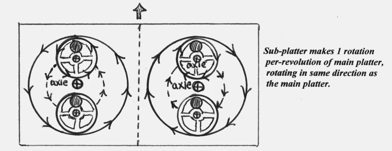
FIGURE 10a- Counter-rotating Platters w/ Off-set, Rotating
Eccentric Sub-platters Used to Take the Place of the Free-swing
Weights. Multiple geared
sub-platters are used to mimic the centrifugal action of Gilbert
device. Although outward throw momentum is reduced, this is Forced
Harmonic Motion and not limited to low or specific speeds.
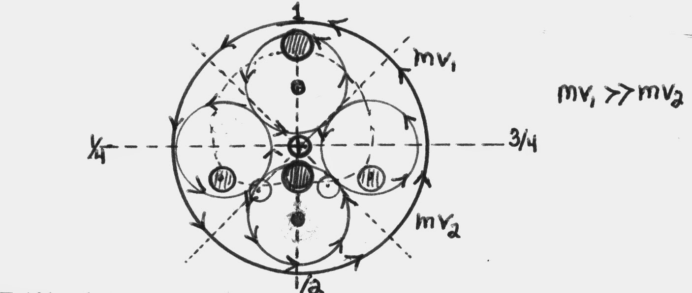
FIGURE 10b - Orbital Positions of Sub-Platter Masses -
Note significant offset of net
momentum/mass. One to four+ sub platters can be used with very
little re-engineering.
Because of the large amount of energy stored in high speed
flywheels, this type of system may represent the best interim device
for demonstrating and creating a functional inertial drive by
mechanically low-tech means; that is, until the phenomena can be
further amplified by more high-tech means; i.e., plasmas and
phased electro-magnetic induction.
Magnetohydrodynamically Driven Liquid and Plasma Inertial
Drives
Directional inertial drives can also be created by forcing
conductive liquids (i.e., mercury, superfluid ferrofluids)
or plasmas to counter-rotate in tube raceways that are geometrically
shaped to create differential momentum via the Venturi Principle.
Propelling the liquid or plasma in such a device can be done by
magnetohydrodynamics, so that the only moving parts are the
conductive liquid or plasma. Total momentum is conserved within such
a system, but directionality is not; i.e., action momentum is
more-or-less linear and central while reaction momentum is
distributed as a series of radial vectors in multiple directions
along the larger curve. Multiple tube arms may be used in
such a device and other mag-drive coils can be used to steer/alter
the action directionality of the device. The following
schematic is of a two-arm device:

FIGURE 11: Liquid Metal or Plasma Inertial Drive -
Note that the geometry of this
device resembles an ovoid magnetic field. Ultra high-velocity metal
plasmas interacting with electro-magnetic propulsion (Lorentz Force)
systems may be the first step towards more advanced inertial or warp
drives. Or, perhaps high gauss electro-magnetic fields can be
manipulated thru varying strength, directed flux, and pinching to
have a similar effect.
DISCUSSION
Prior to this point I have neglected to include the mathematical
principles of the devices I have discussed. This is mainly because
most accepted mathematical descriptions are essentially tautological,
conforming to accepted laws and principles of motion and momentum;
thus useless in describing any new concepts that would violate those
principles; i.e., “mathematics will lead you only to the logical
conclusions of your basic assumptions” (Stine, 1969). However,
there are mathematical transformations of accepted laws (hard won
from engineering experience) that can explain the discussed
phenomena, and in this section I will discuss these proposed motion
law transformations as well as discuss some of the implications of
inertial drives when used as impulse engines or possible warp drives.
The basis of unidirectional impulse from angular rotation (discussed
in the previous sections) has best been described by theories
invoking the concept of the Critical Action Time; a concept
conceived of (directly or indirectly) by many physicists of
excellent reputation and credentials; i.e., William O. Davis,
Hermann Von Schelling, Henri Coanda, Serge Korff, Gilbert Plass, and
several others (including Werner Heisenberg). The development
of the theory, however, can be credited directly to W.O. Davis
(1962a,b, 1967), who worked out the mathematics of the phenomena
based upon real-life engineering experience and modification of the
Newtonian equations/laws. The general principle of the critical
action time (CAT) is “that the energy of a system
cannot be changed in zero time”, or, “that there is a time in
which a system as a whole cannot accept energy (input)”. This
concept essentially says that whenever the rate of energy input into
a system is too great for the system to absorb, the excess energy
must either be excluded or leave the system; either by translating
the energy to another system and/or changing the form of the input
energy so that it may be radiated away (Davis, 1961, 1962,1967).
Davis’s revision of the basic Newtonian equation for applied force
in one direction opened the door for a theoretical inertial drive
effect by: 1) adding a third derivative containing the critical
action time (D), 2) including Hook’s spring constant
(k) in the starting condition, and 3) including a
viscous damping coefficient (V) in the first derivative;
the revised force equation and n=3 summation is:
F = kx + V dx/dt
+ m d2 x/dt2 + Dm d3 x/dt3
The implications of this Newtonian revision (Davis Mechanics)
is that “There is a force proportional to the rate of change of
acceleration as well as Newton‘s force proportional to acceleration
itself”, (called surge: Davis, 1962); thus in systems
with cyclically unbalanced forces and subject to harmonic driving
forces, a unidirectional force can manifest itself through induced
motion of the axle(s) -
ergo, an inertial drive.
Space Drives & Space Warps
What can we expect if an advanced inertial space-drive
system was created and what actual effects would we experience if
theoretical velocities of near-light-speed (or beyond) are made
possible? To create a true interstellar drive, space itself
would have to be warped/foreshortened in the direction of travel
without involving the space vehicle or its’ passengers in the
consequences of relativity (internal momentum). This may be possible
by experimenting with the various manifestations of momentum and the
actual effect they have on the fabric of space-time. Cutting to the
chase, it may be possible to create a asymmetrical “warp” in the
fabric thru forced harmonic motion and perturbations of momentum in
high speed angular acceleration.
In Einstein’s Equivalence Principle, the (apparent)
force of gravity (mg) is the same as the force
produced by linear acceleration/deceleration (mD
v) and angular acceleration (ID
w ). But he also
believed that gravity was a phenomenon created in the fabric of
Space-Time, where mass warped or proportionally distorted this
fabric rather than being an actual attractive force mediated by
gravitons. Therefore, if the force of gravity creates a
4d warp in space-time, this means that the forces of linear
acceleration, deceleration (ma /-ma), and angular acceleration (ID
w ) also produce warps
in space-time if they are in fact equivalent to g. In the following
diagrams, deceleration is viewed as two possibilities; one as a
positive warp ahead of the decelerating object, the other as a
negative warp behind it (negative acceleration). The
conceptual difference between these two possibilities may be quite
significant in being able to form a propulsion warp effect.

FIGURE 12 - Space Warp Gradients Produced by Mass, Linear
Acceleration, and Deceleration/ Negative Acceleration.
Angular acceleration can be viewed as a unique g warp case,
but its attractive Fg
effects can be tested for by duplicating Cavendish’s
experiment for deriving the Gravitational Constant (G),
but using a high speed flywheel rather than a second large mass.
With this modified experiment, any significant virtual mass
increases could be determined by measuring potential g gradients at
different positions around the flywheel.
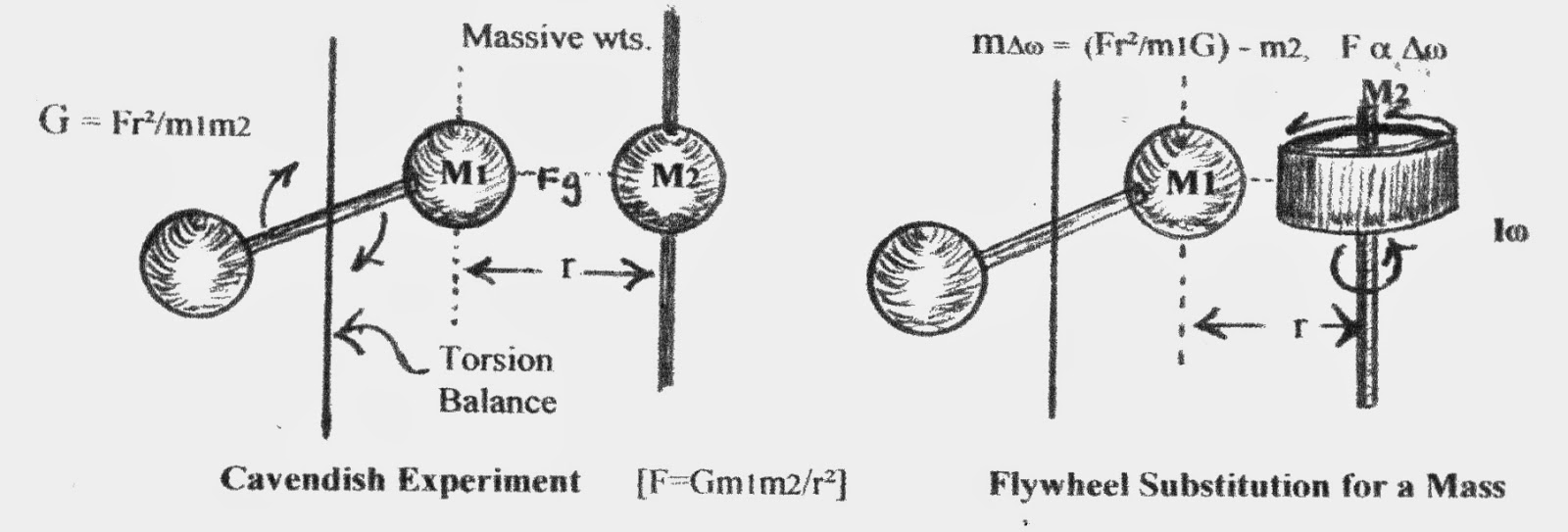
FIGURE 13a - Substitution of a Flywheel for Mass in The Cavendish
Experiment
If there is increased attraction between the flywheel and the
torsion mass as the speed of the flywheel is increased, then it may
be possible to harness this phenomena (via displaced virtual cgs
and offset momentum) to create a warp ahead of a space
craft for it to “fall“ into; i.e., directional movement without
actual action/reaction propulsion.
Figure 13b is a diagram of angular momentum/ outward g force as
it increases from the axle to the rim of a gyroscope/flywheel at
constant angular velocity [F(Iw
) = r /r²
]. In it you see 0 g force at the axle and then an exponential
increase in g force to a maximum at the rim. Beyond the rim, g force
again drops to zero, but does all the “attractive” g force also drop
to zero?; i.e., if g forces create a dimple in the space-time fabric,
is there any dimple gradient beyond the rim edge? The above modified
Cavendish experiment should be able to test this theory. Perhaps by
creating displace cg’s (virtual cg’s) thru variable momentum we can
create such a dimple gradient and make a useable warp in space-time.
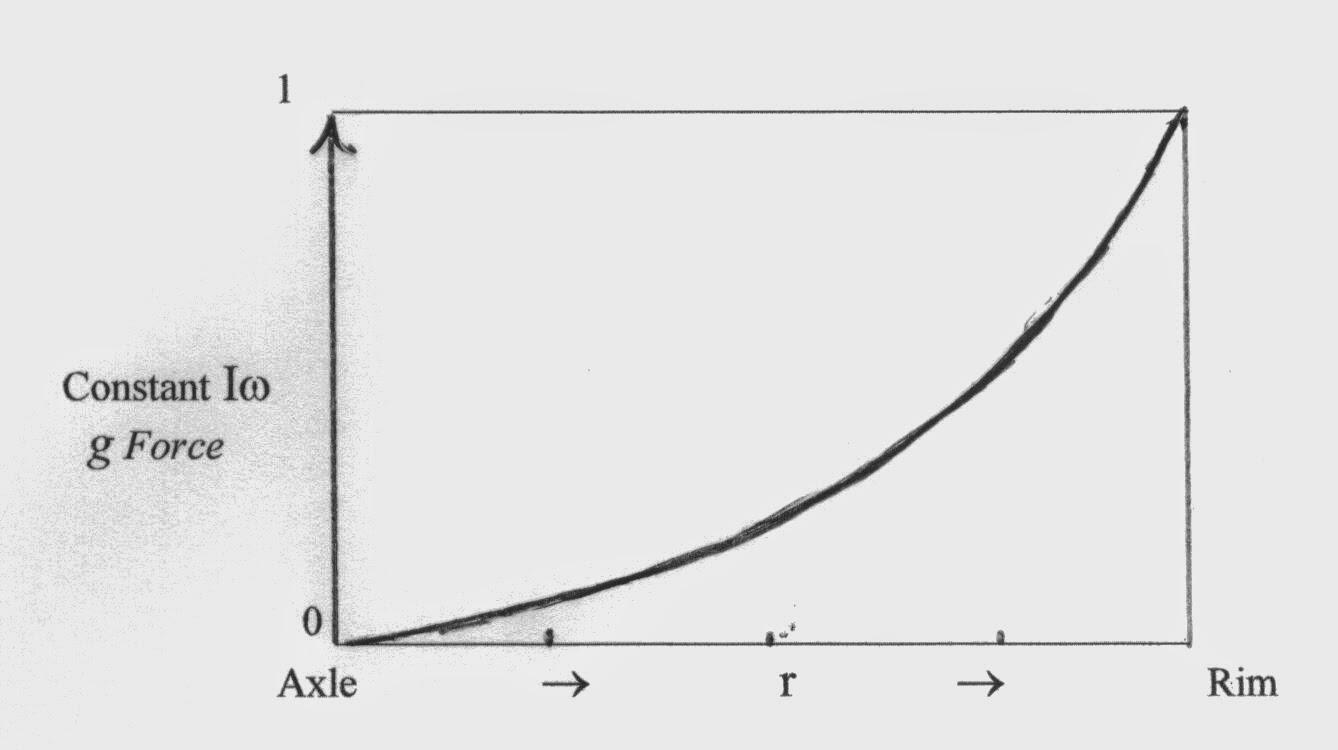
FIGURE 13b - Increase in g from Axle to Rim in a
Flywheel at Constant Velocity -
r = distance from axle; Iw =
angular momentum r(g force).
The second figure (14b.) in the following diagram is a space-time
warp proposed by the Mach Principle / Woodward Effect
and Alcubierre’s theoretical warp engine. However, angular
acceleration devices like that proposed in Figs. 10 & 11 could also
create this kind of space-time warp.
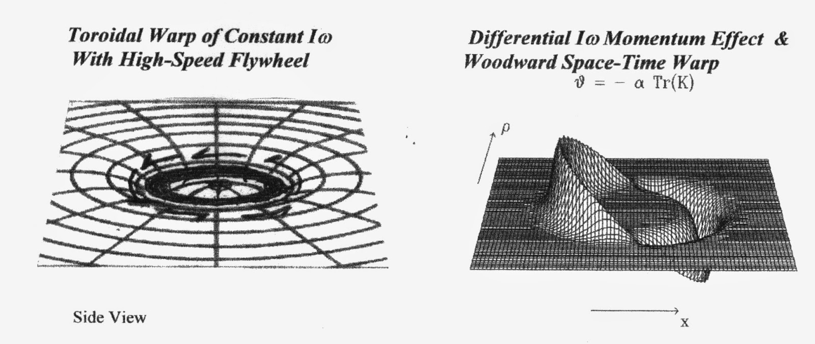
a. b.
Figure 14a&b - Angular Momentum & Proposed Space-Time Warp
Effect of Off-Set Momentum Device (see Fig. 10)
Note that the g effects drop off as
the center of rotation is approached in both effects. Also note that
the Woodward Effect warp favors a negative acceleration
interpretation of deceleration momentum.
In Figures 12 & 14, the effects of mass / acceleration on the
fabric of space-time (Higgs Field?) act as if space-time were
a non-trivial medium that was creating g drag on an
accelerating mass and producing an effect like the wake or bow wave
of a boat; or, as if the inertial mass was being attracted
towards some dimension beneath a space-time interface / the
Higgs Field. The effects of deceleration (negative
acceleration) on this fabric seem to be the most telling and may
demonstrate an actual negative g force / space-time warp
effect.
Electromagnetic, Magnetic, and Gravitational Attraction
If gravity and acceleration warp the fabric of space-time,
what about electro- magnetism and magnetism? We know electric
charges add to the mass of a particle, and that magnetism as a force
behaves similarly to gravitational force and can be alternately
described by substituting the strength of two magnets for the masses
in Newton’s gravitational equation. However, unlike gravitational
force, magnetism and electro-magnetism have a repulsive nature
depending on magnetic polarity. So, is it feasible that magnetism
and electromagnetism also create a warp in space-time /the Higgs
Field via electro-magnetic induction forces (i.e.,
Lorentz Force)? And, under specific conditions, might
gravitational force also have a repulsive nature, perhaps as
a property of dark matter or negative acceleration?
Fg = G m1·
m2 / r²
~ F(-a) = G m(-a)·
/ r² ~
± F
= A ±
mmf
·
±
mmf
/ r² [mf
= N or S]
Faster-Than-Light vs. Wormholes
Recent experiments have supposedly “accelerated” photons
to velocities measured at over 300 times c, demonstrating that the
speed of light might not be an upper limit to velocity. However, as
photons are supposed to be mass-less, but have momentum, perhaps
these photons may have simply had their relativistic “mass”
increased by forcing them to exceed their natural top velocity,
causing them to worm-hole/foreshorten the distance traveled
so they only appear to exceed light speed. Or, perhaps the
speed of light is not the ultimate speed limit in the
universe, but only the velocity limit of the normal space-time
universe. There have been proposed theoretical quantum “particles”
that travel beyond the speed of light, i.e., tachyons or neutrinos
with tachyon nature; which would have space-like rather than
time-like four-momentum. In the tachyon dimension,
deceleration theoretically produces acceleration of the particle,
almost as if that dimension was a mirror image of our own 4-dimensions.
Nonetheless, these photon experiments could be the possible proof of
a worm-hole effect if their results are reinterpreted using
Davis Mechanics and General relativity, and by seeing if the photons
actually did have an increase in relativistic “mass“. Thus, if the
speed of light is an absolute constant and unable to be exceeded,
then the foreshortening / compression of space-time via a wormhole
would be the most logical explanation for apparent faster-than-light
travel; (perhaps photons are just wavicles in/of the Higgs Field?).
According to the Theory of Relativity, when a non-zero mass
particle (or a spaceship) approaches the speed of light (c) it
experiences an exponential slowdown of time and a contraction along
its’ direction of travel. As the speed of light is closely
approached, internal clock time in a spaceship would slow to zero
and the direction of travel distance would also appear to shrink
towards zero; plus it would require an infinite amount of energy to
actually achieve c because of the exponential kinetic mass
increase. Be that as it may, at c, an observer (in the ship) would
not experience any passage of time, and distance in the direction of
travel would appear to be zero; so they would essentially travel to
the end of space-time at the instant c was reached. Such an object
would also experience an exponential increase in momentum energy
towards the infinite (that is, according to Lorentz transformations
in Relativity theory). This is where I believe the Theory of
Relativity may break down, and may not actually represent reality at
c or at hypothetically greater (superluminal) velocities. In theory,
the warp created in space-time when trying to reach c might actually
create a bubble outside of normal space-time, and not be
subject to the limitations imposed by relativity theory; i.e., time
dilation, continuous and exponential relativistic “mass” increase,
or internal g forces.
Relativity and The Mass-Velocity Barrier
According to conventional relativity theory, before any non-zero
mass object could come close to achieving the speed of light and
infinite kinetic mass, it would come up against the space-time
curvature limit for massively dense objects; i.e., the creation of a
black hole IAW General Relativity via Schwarzschild’s equation for
the space-time curvature (Ω
- see Fig.14 & 15):
rs
= 2Gm/c2 à
m = rs c2/2G.
Yet, since the objects’ mass/momentum increase is due to its’
velocity approaching c, it should be a vector quantity. Thus
time-space curvature should also be a vector quantity in the
direction of travel and create a worm-hole rather than a
black hole. As the speed of light was approached, distance and time
in the direction of travel would continue to contract. The closer to
c the velocity was, the greater the relativistic momentum mass (r
r) and contraction of space-time
in the direction of travel, until it would approach infinite
r , 0 d, and 0 t at c. Even
still (acknowledging Relativity Theory), c would be any non-zero
mass’s ultimate velocity limit, even though distance traveled per
unit time would have the appearance of being faster than
light; and this may be (again) an alternative explanation for the
experiments where photons were (apparently) pushed to faster than
light speed. So, does the Theory of Relativity breakdown at the
speed of light and superluminal velocities, just as the laws of
physics breakdown beyond the event horizon of a blackhole, or as
Newtonian starting assumptions need to be amended at highr
velocities even well before relativistic velocities are
approached? The following diagram shows how velocity is limited by
the speed of light while kinetic mass/energy continues to increase
exponentially (with equivalent energy input); that is, until
a space-time curvature limit is reached.

Relativistic Mass/Momentum/Energy (exponential)
Figure 15 - Velocity and Relativistic Momentum Limits -
Each graph point is a factor 10
increase in kinetic energy/momentum mass; which increases until the
space-time curvature limit and production of a blackhole or worm-hole:
PW = 2Gm/(v/c)²=
Rc²/2G
Wormhole Effect
Relativity Theory predicts that momentum-mass would grow
proportionally to the energy needed to propel the object to near
light speed, i.e., m=e/(v/c)2. But what happens
when the upper limit for mass/dimensional density is reached? Since
the “mass” increase is due to linear acceleration/ relativistic
momentum (a vector quantity), would we get a black hole or a
worm hole? The following diagram is a modified Lorentz
Transformation diagram reflecting the upper limits for mass
density or relativistic momentum (ala Schwarzschild radius
R):
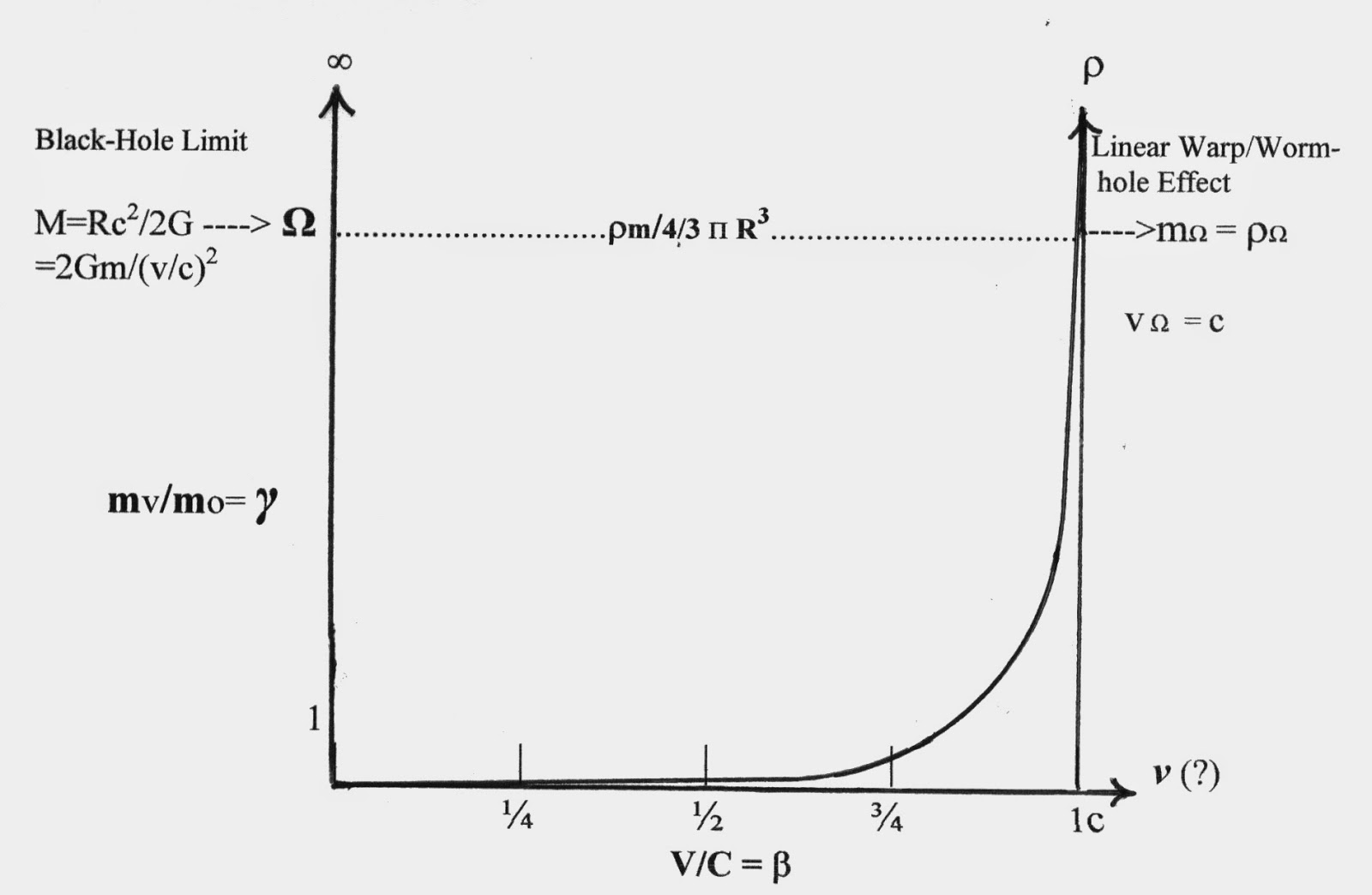
FIGURE 16 -
Modified Lorentz Diagram
- Momentum/mass increases as a function of velocity
(r) but encounters a limit
(Ω)
where a worm hole should be created. R= Schwarzschild radius,
γ
=
Lorentz factor,b
= v/c, mΩ
= m/4/3 pR3=
mass density limit, G=Gravitational constant, M/r=
relativistic mass/momentum, m = moving mass, mo = rest mass, v =
velocity, c = speed of light.
Lorentz Factor and Blackhole/Wormhole Effect (γ=
1/ Ö1- (v/c)2)
Relativistic “Mass” (momentum):
mr = m
Ö1- (v/c)2
----> r = mov/
Ö1- (v/c)2
Mass limit ®
Black-hole or Worm-hole:
c = Ö2GM/R
---> vG
= ÖGM/r
--->vG
= c ÖR/r
M = Rc2 /2G ---> mo
= 2Gm/(v/c)2 ---> v = c
Ö2Gr
/mo
or:
vΩ
< c ~ Ö2G moΩ
---> moΩ
= vΩ
2 / 2G »
r
W /4/3p
R3
There also seems to be an interesting connection between
mass and time within General Relativity and the
Equivalence Principle. It would seem that they are inexorably linked
as part of the four-dimensionality of space-time. Mass-less or
virtually-mass-less particles that travel at (or close to) the speed
of light appear to be timeless, that is, the moment of their
creation is the same as their moment of extinction. From the
perspective of a particle at c, there is no time nor distance/third
dimension. Mass, on the other hand, almost always seems to have time
and three dimensions associated with it (with the exception of a
black-hole?). Thus time appears to be a basic property of mass
within the normal space-time universe, describing its‘ interaction
with a Higgs Field.
Paradigms, Paradoxes, and Reality
One problem I see in interpreting Relativity
Theory is with the paradoxes that seem to occur at and beyond c.
Paradoxes, however, can actually be seen as just the limitations or
descriptive limits of the paradigms, not prohibited
realities; as reality is what it is independent of a paradigm’s
ability to describe or account for it. Therefore, when we
encounter an apparent paradox, we probably need to re-examine and
adjust the paradigm, not deny the reality. For instance, the
Twins Paradox is not really a paradox if the twin who journeyed
close to the speed of light did not return younger than before he
left. Even transatlantic jet travelers and astronauts
experience a slower passage of time compared to the earthbound and
stationary. Relativity paradoxes are then just different comparative
realities created in different inertial/mass reference systems.
Another problem is that of supposed causality violations and
hypothetical backwards time travel. However, any particle, no matter
how fast it travels, arrives at a distant location after it
departed, not before. After all, photons don’t travel
backwards in time (unless photon acceleration experiments can
actually demonstrate this), and quantum teleportation is
instantaneous and yet allowed without violating causality.
Analogously, a supersonic jet or rifle bullet arrives ahead of it’s
sonic boom or report sound, so who’s to say that a
superluminal object can’t physically arrive ahead of its’ light and
not violate causality, just appear to do so? After all, the light we
see from distant stars and galaxies is what happened thousands,
millions, or billions of years ago, not their present position /
state of existence; so what we see is not what is, but rather
what/when it was. Maybe there actually is some kind of universal
reference field in the Universe (Higgs Field / Mach
principle?), one created by the interaction vector sum of all
mass/energy (M)
in the universe acting on the mass/energy at a particular position
in space-time (Ñ Fg
= G Ñ
ò mM/R²
). This could be the equivalent of a space-time ether.
Or, perhaps the field is a Higgs Field membrane interface
with a dimension of dark matter and energy.
Conclusions
If we conceptually integrate Davis
Mechanics and inertial drive experimental results with Einstein’s
Equivalence Principle, the Mach Principle, the Higgs
Field concept, and the Woodward /Alcubierre Effect /concept, we
can see how virtual faster-than-light travel and warp drives may be
possible. By viewing the space-time continuum as a 4 dimensional
matrix that can be distorted/warped by mass, electro-magnetism,
charge, and the creation of virtual mass (thru acceleration, ma &
Iw), and allow for the shunting of space itself, we may find the
really big loophole in Newtonian and Einstein’s physical laws
that would allow for real-time interstellar travel. As a closing
thought to ponder, what if we (hypothetically) consider the
described performance and behavior of supposed alien UFO’s that have
been seen for centuries… isn’t that exactly the kind of supposedly
impossible flight characteristics we would expect from an inertial
warp drive that doesn‘t rely on action-reaction propulsion?
ADDENDUM
The Time
Quantum
The deterministic treatment of applied force and other
revisions in the Laws of Motion (Davis Mechanics) allows one to
calculate the smallest meaningful interval of time for any finite
system (6.27x10- 24 s) a value also
independently arrived at stochastically by Hermann Von Schelling
(1963), from physical assumptions made by Gilbert Plass (1961), and
from theoretical estimates by Werner Heisenberg (1956). This value
is believed to be a universal constant that determines both the
speed of light (c) and Planck’s Constant (h) - both of
which can be derived from this time quanta or
vice-versa using Davis Mechanics. By accepting the existence of a
time quanta, we can now make sense of why certain constants are
constant. For instance, the speed of light c (as a velocity) is a
constant composed of distance per unit time (d/t), meaning that both
of these factors or dimensions must vary in concert as a
quintessential manifestation of the space-time continuum. A time
quantum would mean that time (based on our concept of space-time) is
not a continuous dimension, but rather one of fixed moments /
instants separated by a mathematically infinite number of
intervening instants or probability distributions. Is this perhaps
(conceptually) how the multi-verse works? … Not as a continuum, but
as 3 dimensional moments or instants (like frames in a motion
picture), and where intervening non-moments are outside of our
space-time frame of existence; yet the separated instants providing
the retrospective illusion of a continuous 4th
dimension.
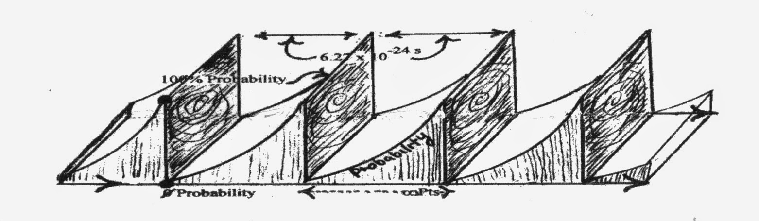
The probability distributions between time quanta would likely
resemble a sine-like wave, with 0 probability after one time quantum
followed by a growing probability distribution until the next time
quanta occurred, “fixing” that particular moment. This process
would be driven by probability and fixed by entropy, meaning that
backwards travel in the same time stream (arrow of time) would be
virtually impossible because of the 0 probability time well after a
time quanta instant.
However, if backwards time travel was
possible, then any attempt to enter a time quantum instant that was
already “written” (past) would have to create or graft on a new time
quanta sequence/ time stream; thus creating an alternate and
parallel universe in a Multiverse. This new universe would diverge
the moment you entered it, and all changes you might make would have
no effect on the sequential series of fixed events in the universe
you left. That is, assuming that present and future events cannot
effect or influence events of the past (as some Quantum Theorists
have proposed). In this perspective, Hawking’s feather-of-time would
resemble a series of connected tufts, with attempts at backwards
time travel creating another fractal pattern in the tuft series (Multiverse).
The following figure is an attempt to show this alternate view.

FIGURE 18 - The Feather-of-Time vs. the Tufted Feather
and the Fractal Feather of a Multiverse Allowing Multiple Realities
and Backward Time Travel.
Hawking’s feather of time is a linear time line with the present
fixing the past and proceeding to one probability or another.
Backward time travel not allowed (unless a new feather is created at
a re-entry point in the past; in which case we would have a
conditional multiverse). Tufted Feather is the same except it is
broken up into a series of stacked feathers with fixed
moments/time-quanta between them. Each probability tuft would
collapse when a new time quantum occurred. The Fractal Feather
allows all probabilities to exist as separate time lines in a
Multiverse, with backward time travel conditionally allowed.
Alternative theoretical values for a time quantum, named a
chronon by Robert Levi (1927), have been derived from quantum
mechanics and General & Special Relativity, and were proposed to
create a theory of quantum gravity. One such value proposed
by Piero Caldirola (1980) is 6.97x10- 24 s,
and is a value very close to that derived by Davis Mechanics. Max
Planck also proposed a universal quantization of time, called
Planck time, but his value was 5.39x10-
44 s. However, the one thing all such theories have in common
is that they all propose a time quantum. Perhaps a
universe with no quantum of time (a continuous unregulated time
frame/ dimension) would come to an end or “run out” soon after it
came into existence; like a clock without a regulated release of
spring energy. Thus the time quantum may be a necessary and
fundamental constant for regulating and maintaining the dimensions
of space-time, the dimension of mass-time, and the existence of our
universe.
If the speed of light is a constant because of the time
quantum, then that must mean there is also a smallest meaningful
unit of distance based on the unit values of c and h (perhaps the
real dimensions/diameter of a black hole or an electron?); which is
calculated from these constants and Davis Mechanics as 1.88x10⁻¹³
cm (Davis, 1963; Heisenberg, 1956).
REFERENCES
Campbell, John W., (1960). The Space Drive Problem.
Analog Vol. LXV No. 4, June: 83-106.
Caldirola, P. (1980). "The introduction of the chronon in the
electron theory and a charged lepton mass formula". Lett. Nuovo
Cim. 27 (8): 225–228.
Davis, William O., (1962). The Fourth Law of Motion. Analog
Vol. LXIX No. 3, May: 83-104.
Davis, William O., (1967). The Energy Transfer Delay Time.
Annals of the NY Academy of Sciences, Vol. 138, 2: 862-863.
Davis, W.O., (1961) Some Unusual Implications Inherent in the
Huyck Dynamic Systems Research Program. Huyck Corporation
report, @1961.
Davis, W., Stine, H., Victory, E., & Korff, S., (1962). Some
aspects of certain transient mechanical systems. American
Phys. Soc., FA10; Spring Meeting. Wash. DC, April 23.
Dean, Norman L. (1959) US Patent # 2,886,976 - System for
Converting Rotary Motion into Unidirectional Motion. US
Patent Office, Wash. DC.
Encyclopaedia Britannica, Macropaedia Vol. 11, (1979). Mechanics
of Complex Systems, (Principle of virtual work; Spinning tops
and gyroscopes). Ency. Brit. Inc., 15th Edition. William Benton,
Pub., Chicago: 777-778.
Gibbs, P (1997) [1996]. "Is The Speed of Light Constant?". In Carlip,
S. Usenet Physics FAQ. University of California, Riverside. Archived
from the original on 2009-11- 17. Retrieved 2009-11-26.
Gilbert, J. (1985) Harnessing g Forces. Science Digest, Sept. 1985:
14.
Harrington, Craig. http://www.inertiaHarringtonlpropulsion.com/
Inertial Propulsion Engine. A Functional Dean Drive. 12/18/2011.
Hawking, Stephen. A Brief History of Time. Bantam Books, N.Y. 1988.
Heisenberg, Werner (1958). Physics and Philosophy. Harper & Bros.,
NY.
Hudson, A.& Nelson, R., eds. (1982). Center of gravity/ Center of
mass; The gyroscope.
University Physics. Harcourt, Brace & Jovanovich, Inc., NY: 215-219;
250-253.
Lévi, Robert (1927). "Théorie de l'action universelle et
discontinue". Journal de Physique et le Radium 8 (4): 182–198.
doi:10.1051/jphysrad:0192700804018200.
Margenau, Henry (1950). The Nature of Physical Reality.
McGraw-Hill.
Plass, Gilbert N., (1961). Classical Electrodynamic Equations
with Radiative Reaction. Review of Modern Physics 33: 37-62.
Renner, Edward (2013). “Forced Harmonic Motion in a Counter-Rotating
Dual Platter System With Eccentric Rotating Sub-Platters”.
Unpublished Design Prototype Paper.
Stine, G.H., "The Rises and Falls of Henri-Marie Coanda", Air & Space Smithsonian, Sept. 1989
Von Schelling, H., (1963). Stochastic Approach to the Laws of Motion. General Electric Co., report No. 63GL106. Advanced Technology Laboratories, July 1, 1963.
Von Schelling, H., (1955) Statistische Modelle als Hilfsmittel der Naturbeschreibung. Mitteilungsblatt fuer Mathematisch Statistik 7: 173-192.